Remove existing handle, woodruff key and leadscrew bearing block.
Unscrew the leadscrew from the leadscrew nut.
Wrap a good thickness of cloths around the leadscrew.
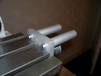
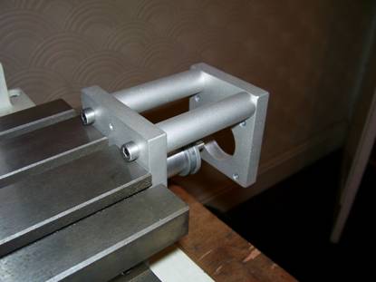
Grip leadscrew in vice with the keyway slot uppermost. See Photo 1 and 2 below.
Photo 1.
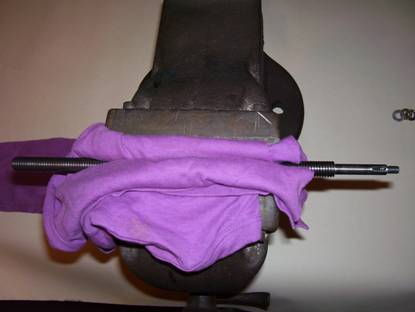
Photo 2

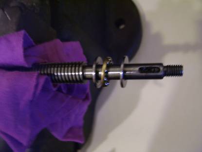
Fit thrust bearing to leadscrew taking care to place the face of the flat race parts of the bearings with the ball groove in them against the cage carrying the steel ball bearings and pack with grease. See photo 3 below.
Photo 3.
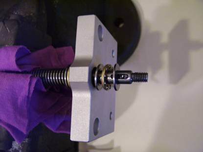
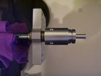
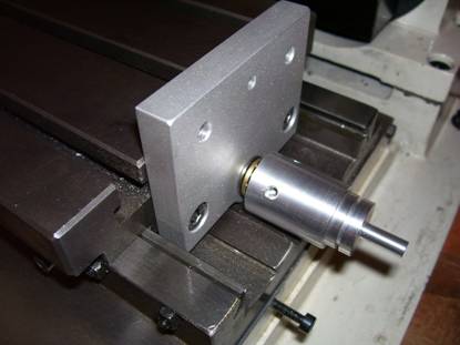
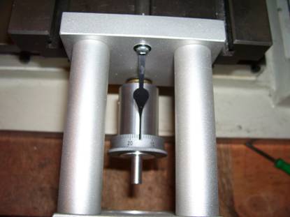
Fit table mounting plate to leadscrew with the counter bores for the cap screw heads NOT facing the vice. See photo 4 below.
Photo 4.

Fit thrust bearing to leadscrew taking care to place the face of the flat race parts of the bearings with the ball groove in them against the cage carrying the steel ball bearings and pack with grease. See photo 5 below.
Photo 5
Fit leadscrew adaptor and tighten up gently by hand until the end float is just taken up without any undue pressure on the thrust bearings.
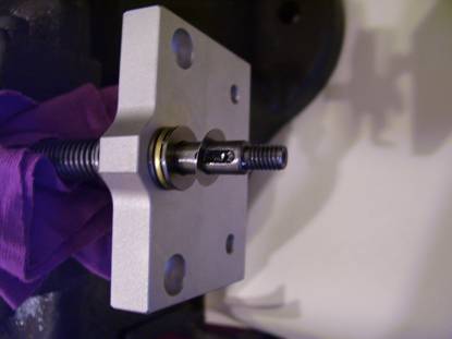
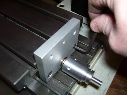
Check to see if one of the radial screw holes land on the top in line with the keyway slot in the leadscrew. See photo 6 below.
Photo 6
Ideally you want the adaptor to be tightened up so as you have to just nip it up with a little load on the bearing to bring the radial tapped hole in line with the keyway without binding the bearing. The thread on the end of the spindle is M6 x 1mm pitch. There are 4 radial holes around the body of the leadscrew adaptor. This means that the leadscrew will move up 0.25mm between each hole. There are a set of shims supplied with the kit which are 0.20mm thick. This means that if you fit a shim between the thrust bearing and the leadscrew adaptor and tighten the adaptor up again then the adaptor will be 0.2mm further away from the bearing which will move the holes further around relative to the key way.
If there is no tapped hole in line with the keyway then remove the adaptor, fit a shim, refit the adaptor and nip it up again. See Photo 7 below.
Photo 7
If there is still no hole in line fit another shim and refit the adaptor. Continue to do this until a screw hole is in line when the bearing is just nipped up or you have fitted 4 shims. Fitting 5 shims will bring you back to the starting position and accomplish nothing.
It might not be possible to get one of the screw holes exactly in line with the keyway in the leadscrew when it is just nipped up. If so find the hole which is closest using the shims without going past the keyway and tighten by hand until the screw hole lines up with the slot. You should be able to find one which does not cause the bearing to bind. See photo 8 below.
Photo 8

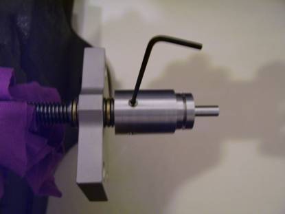
Finally, fit the dog point screw into the adaptor and lock up into the keyway slot. See photo 9 below.
Photo 9
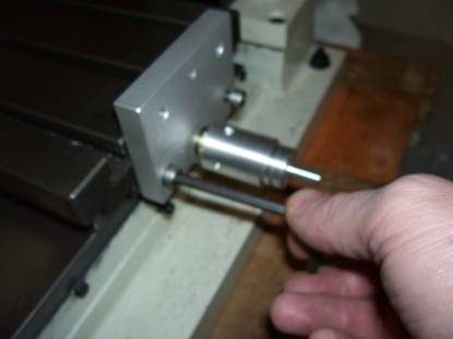
Grease leadscrew and screw leadscrew back into machine. See photo 10 and 11 below.
Photo 10

Photo 11

When the table mounting plate is near the edge of the machine bed slide the table up to the table mounting plate and fit the M6 cap screws. Tighten the screws up and then slack them off slightly to allow the plate to move slightly. See photo 12 below.
Photo 12
By turning the leadscrew adaptor screw the table along right up to the leadscrew nut as far as it will go then back it off a couple of turns. At this point any misalignment will be at its worst condition. See Photo 13 below.
Photo 13
Now tighten up the M6 screws that hold the table mounting plate to the table. See photo 14 below.
Photo 14
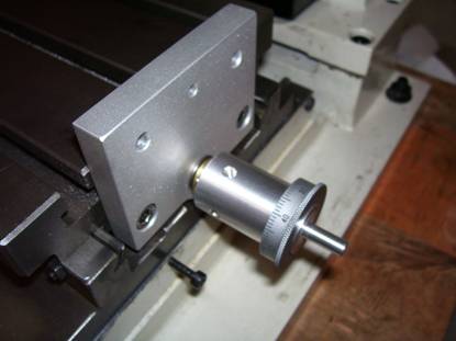
Very carefully remove the machine dial from the Original machine handle. As you slide the dial off a spring clip will pop out so hold your hand around the handle assembly while sliding the machine dial off the handle. Now fit the machine dial and spring clip to the leadscrew adaptor. See photo 15 below.
Photo 15
Fit the standoff spacers and just nip up the screws. See photos 16, 17 and 18 below.
Photo 16
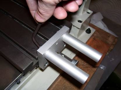
Photo 17
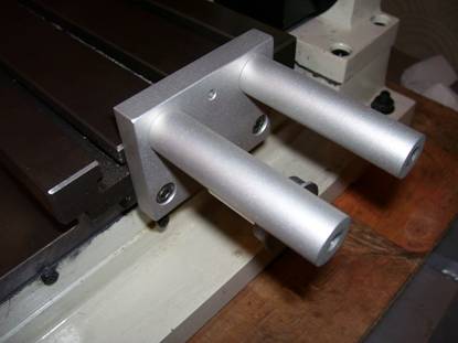
Photo 18
Fit the motor mounting plate and just nip it the screws. See photos 19, 20 and 21 below.
Photo 19
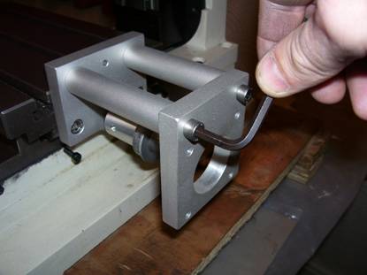
Photo 20
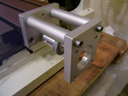
Photo 21
Bend the needle pointer just below the mounting hole so as the tip of the pointer is just over the machine dial and secure with the 3mm screw nut and washer. See photos 22, 23 and 24 below.
Photo 22
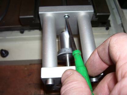
Photo 23
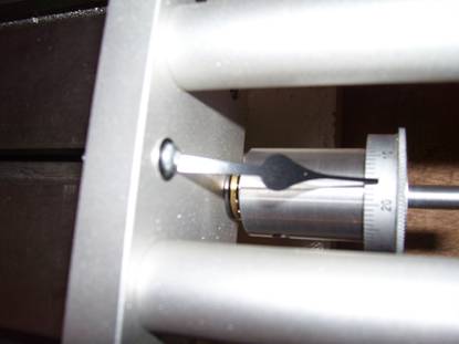
Photo 24
Fit the motor and drive coupler and secure with M5 screws and nuts. See photo 25 below.
Photo 25
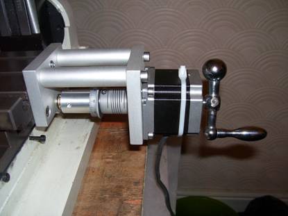
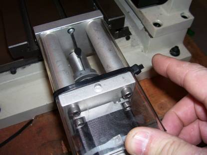
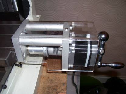
Slide motor cover into position as shown. See photo 26 below.
Photo 26
Slide cable tie through holes in motor cover as shown. See photo 27 and 28 below.
Photo 27
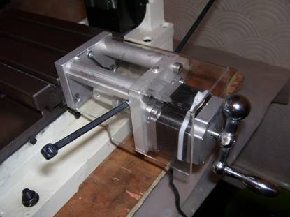
Photo 28
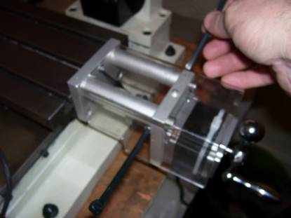
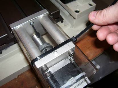
Secure cable tie and pull tight as shown. See photo 29 and 30 below.
Photo 29
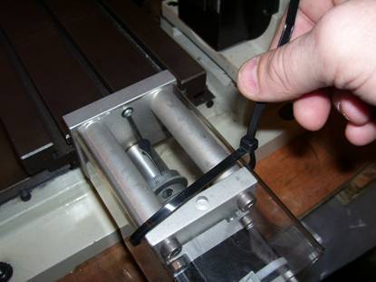
Photo 30
Cut cable tie to length as shown. See photos 31 and 32 below.
Photo 31
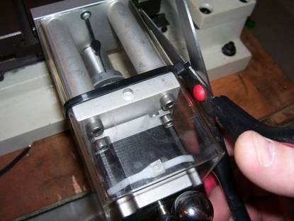
Photo 32